
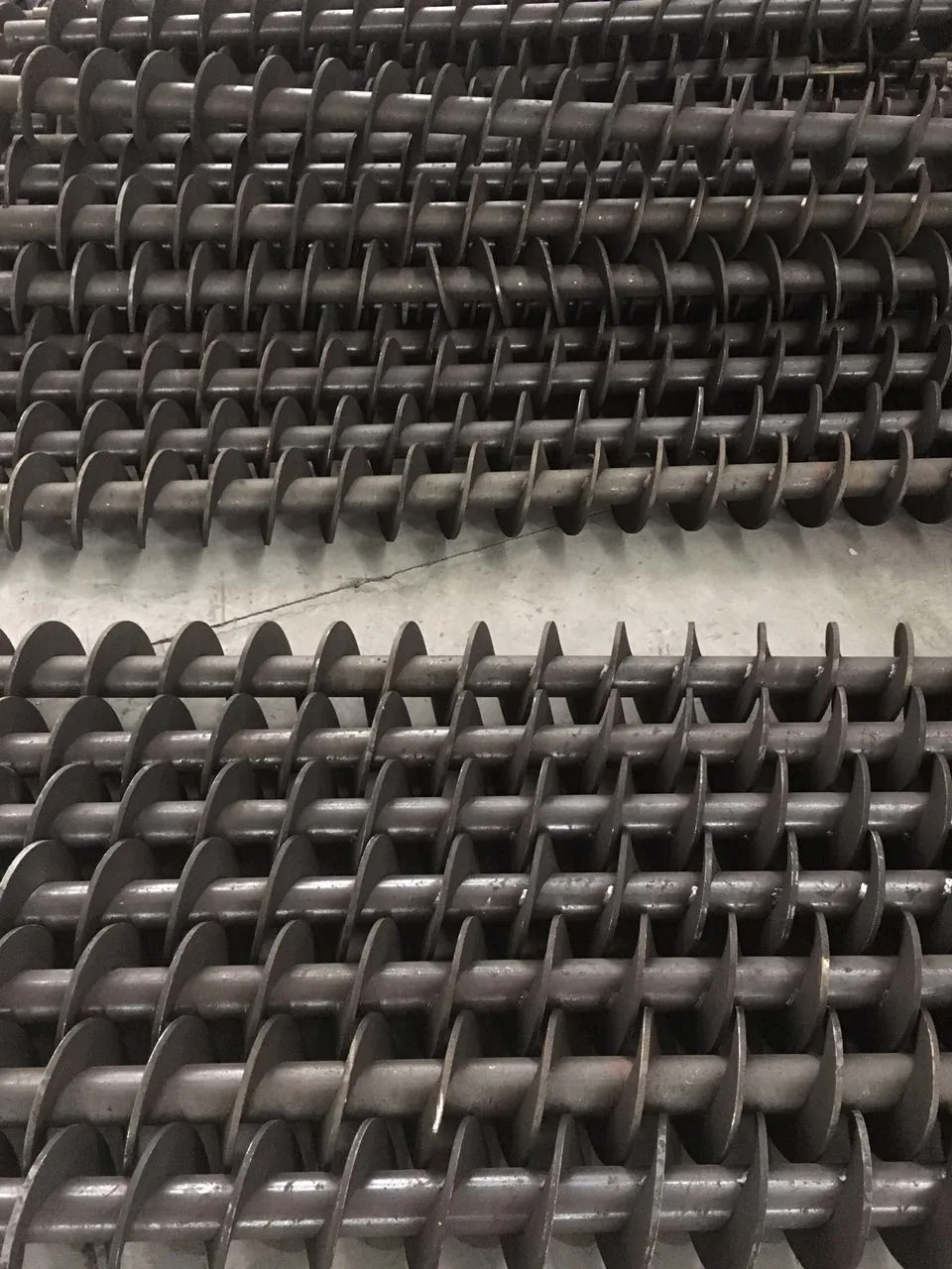
Screw flight
Shafted Auger Assembly
Complete shafted auger assemblies with flighting, centre tube or shaft, welds and end interfaces defined by drawing.
Engineering fit
Built around the dimensions, material and production target that matter
A complete screw component in which the selected flighting is positioned and joined to a centre tube or shaft with drawing-defined ends.
Use the stated range as a practical starting point. We confirm the final configuration against your drawing, material and operating conditions.
Discuss this product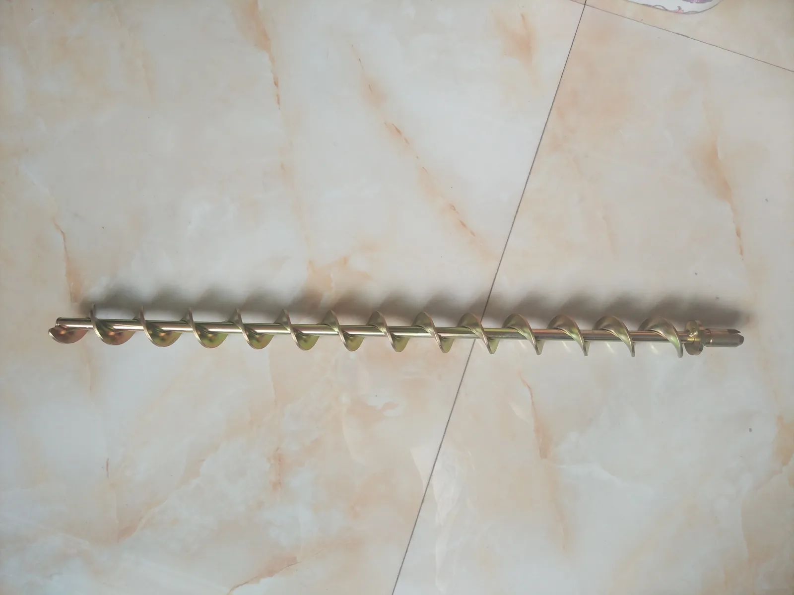
- Replacement conveyor screws
- Feed and material-handling augers
- Drawing-based machine assemblies
Product data
Product Specifications
| Parameter | Specification |
|---|---|
| Flight geometry | Outside diameter, pitch, thickness and hand from the approved drawing |
| Centre member | Tube or shaft diameter, wall or section and material to be specified |
| Overall length | Finished length and flighted length controlled from stated datums |
| End interfaces | Drive, bearing, coupling, journal or flange details supplied by the buyer |
| Joining | Weld location and dimensional requirements reviewed with the assembly drawing |
Workshop reference
Product and process views
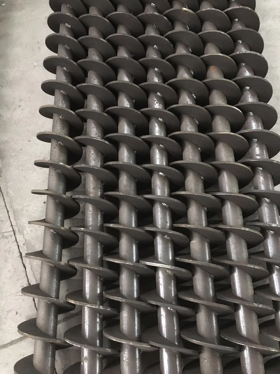
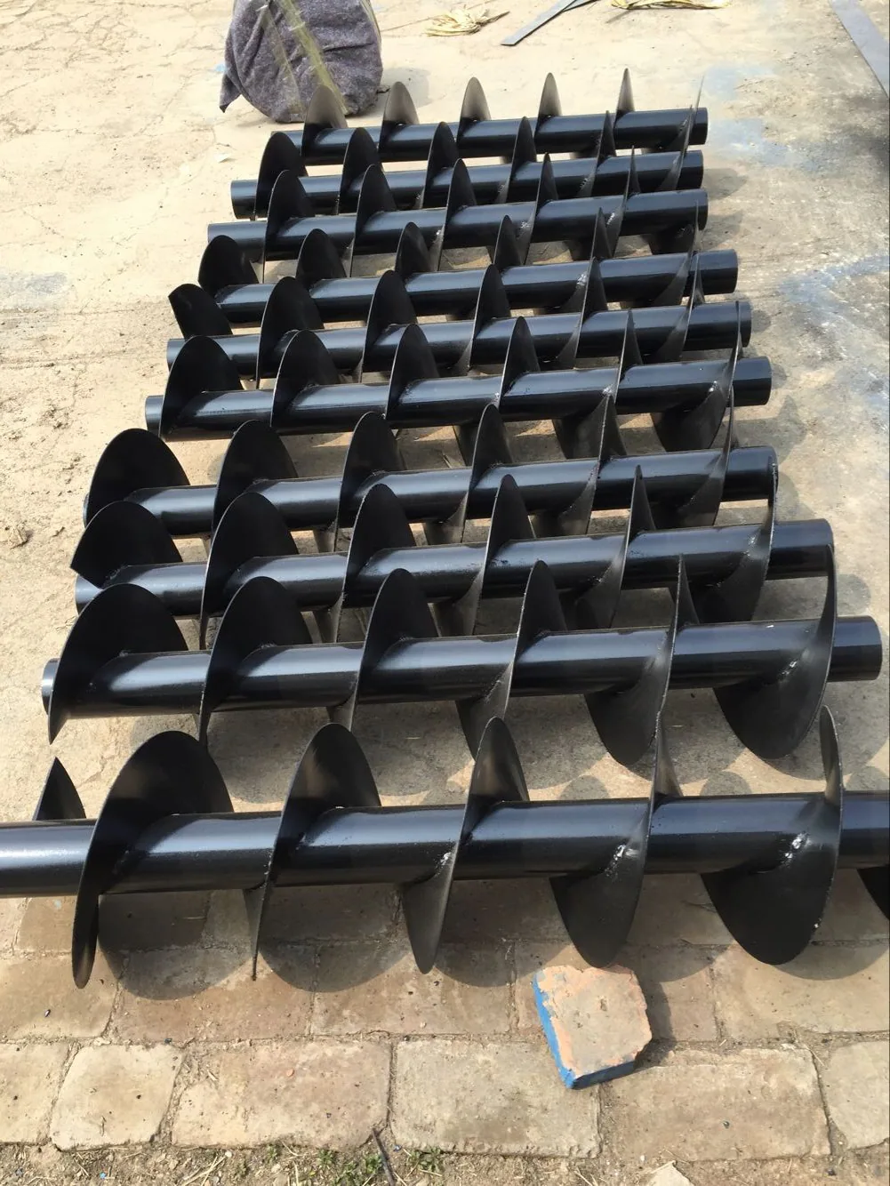
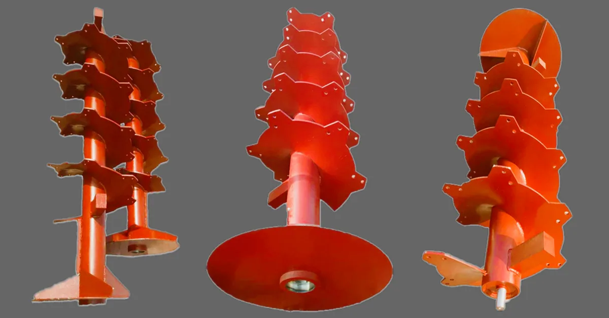
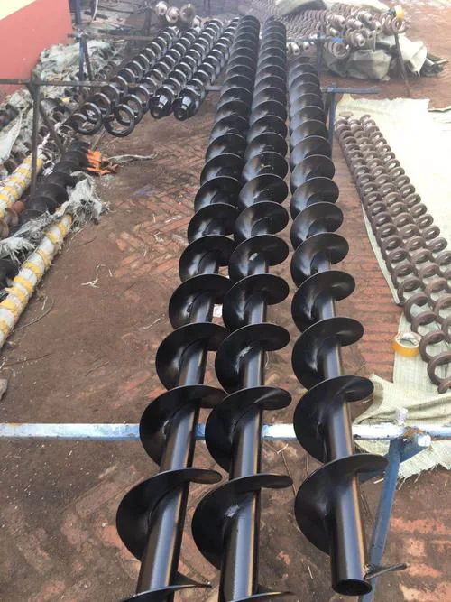
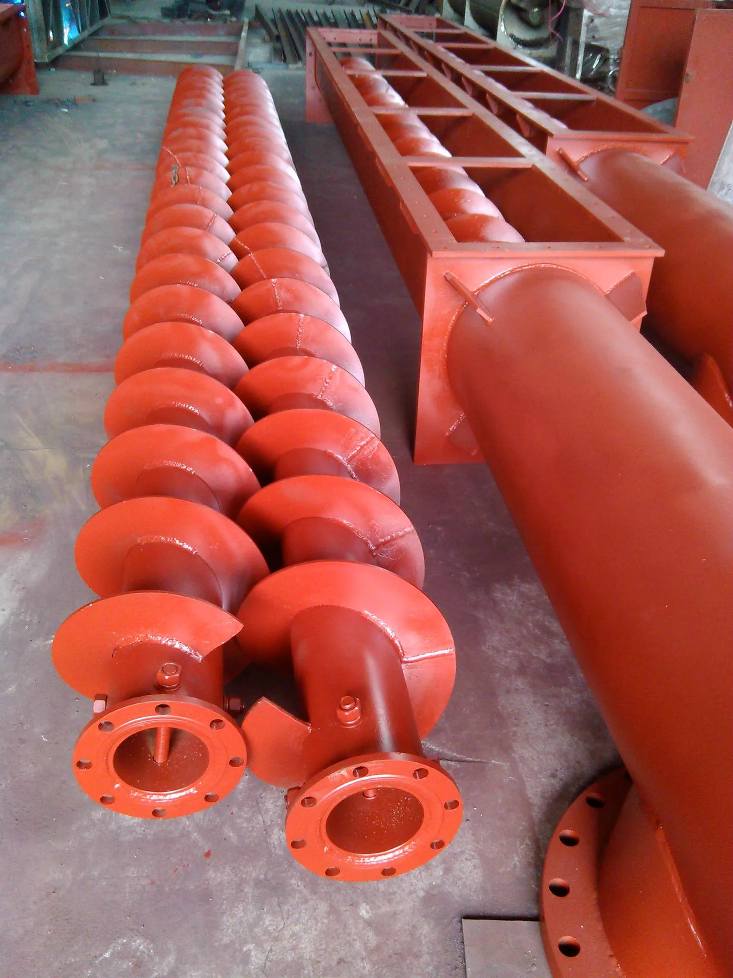
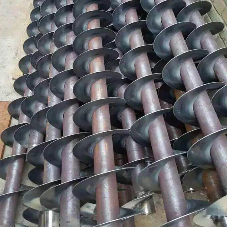
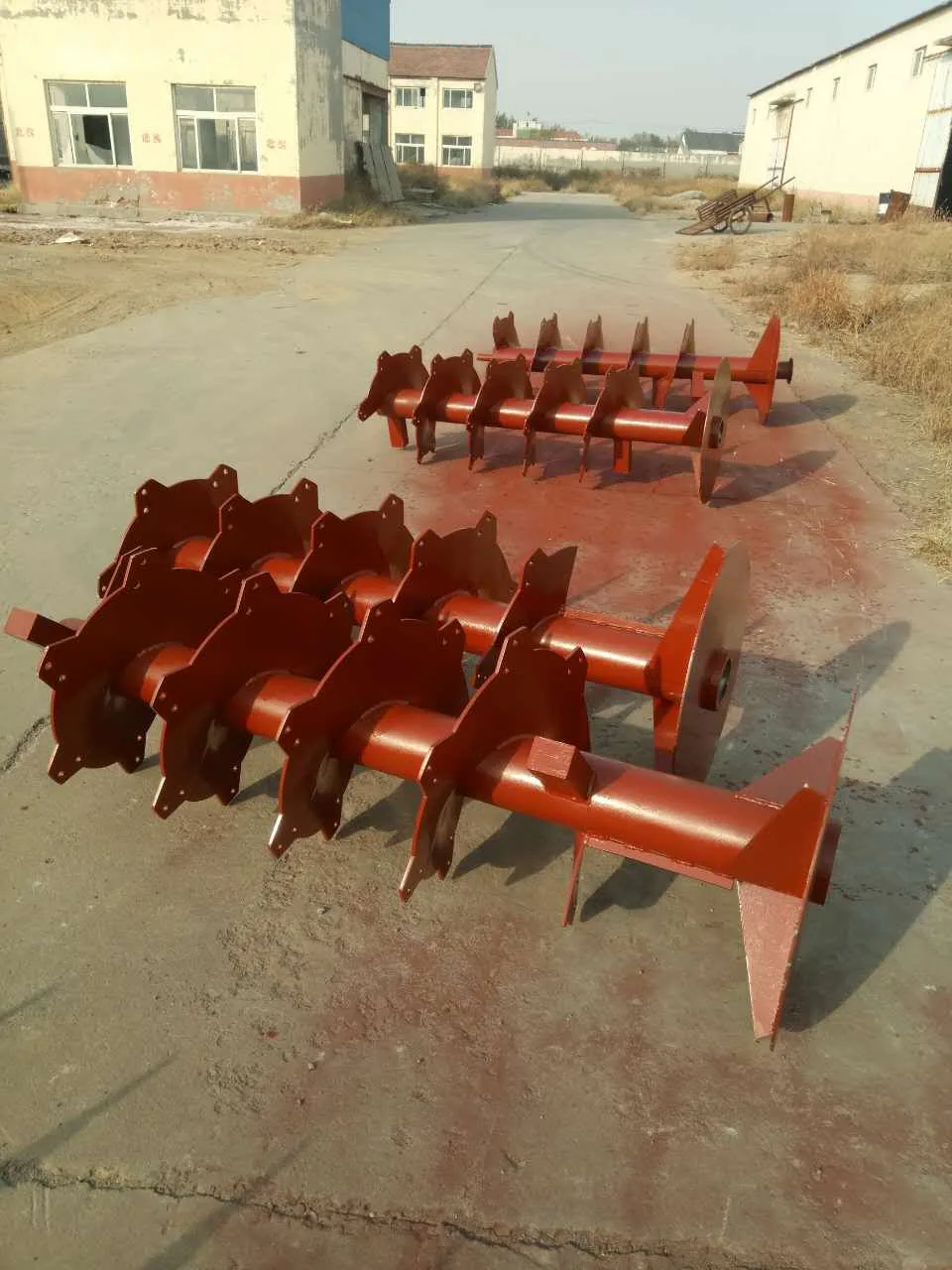
From flight profile to complete screw
A shafted auger assembly combines flighting with a centre tube or shaft and the interfaces needed to install or drive the component. It is therefore quoted from an assembly drawing, not from OD and pitch alone.
Flight and centre member
State the flight outside diameter, pitch, thickness, hand and flighted length. The centre member requires its own material, outside dimension, wall or solid section and straightness requirement. Indicate whether the flight is continuous, sectional or a replacement match to an existing part.
End-interface control
Drive and support ends can include journals, flanges, couplings, keyways, holes or threads. Show these features on the drawing and identify the datums for overall length, concentricity and position. Do not rely on a photograph for a critical mating dimension.
Welding and inspection
Define weld locations and any areas that must remain clear for bearings, seals or couplings. If post-weld straightness, runout or fit is important, include the required inspection datum and acceptance requirement on the drawing.
Quote checklist
- Flight OD, pitch, thickness, hand and flighted length
- Centre tube or shaft size, section and material
- Finished overall length and reference datums
- Drive, support, journal, flange and coupling details
- Weld locations and any machined areas
- Surface or coating requirement, if specified
- Quantity, drawing revision and replacement photographs
- Installation clearance and mating-component information
Before quotation
Frequently asked questions
Use these answers as a starting point. Final geometry, material and equipment scope are confirmed from the project information.
Can you supply the flight already fitted to the shaft?
Yes, when the centre tube or shaft, flight geometry, weld requirement and end interfaces are defined in an approved assembly drawing.
What is needed for a replacement auger?
Provide overall length, flighted length, outside diameter, pitch, hand, centre member dimensions, end details and photographs of the original assembly.
How are drive and bearing ends confirmed?
The buyer should provide dimensioned end details including journals, keyways, holes, threads, flanges or couplings and the required positional tolerances.
Can continuous or sectional flighting be used?
Either route may be reviewed. The choice depends on the geometry, material, assembly method and quantity rather than the finished product name alone.
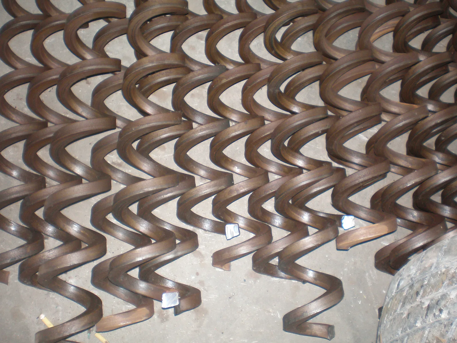
Square-Bar Flexible Auger
A flexible auger made from a square-section profile, with the bar section, coil geometry and installed tube route reviewed as one system.
View details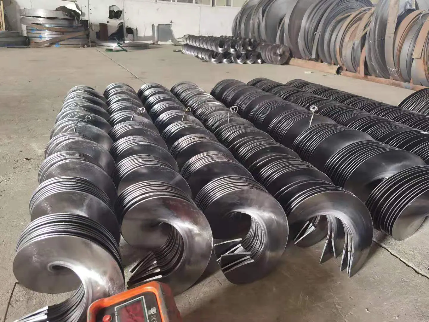
Cold-Rolled Continuous Screw Flight
Cold-formed strip flighting for applications that need continuous, seamless geometry and controlled pitch, diameter and thickness.
View details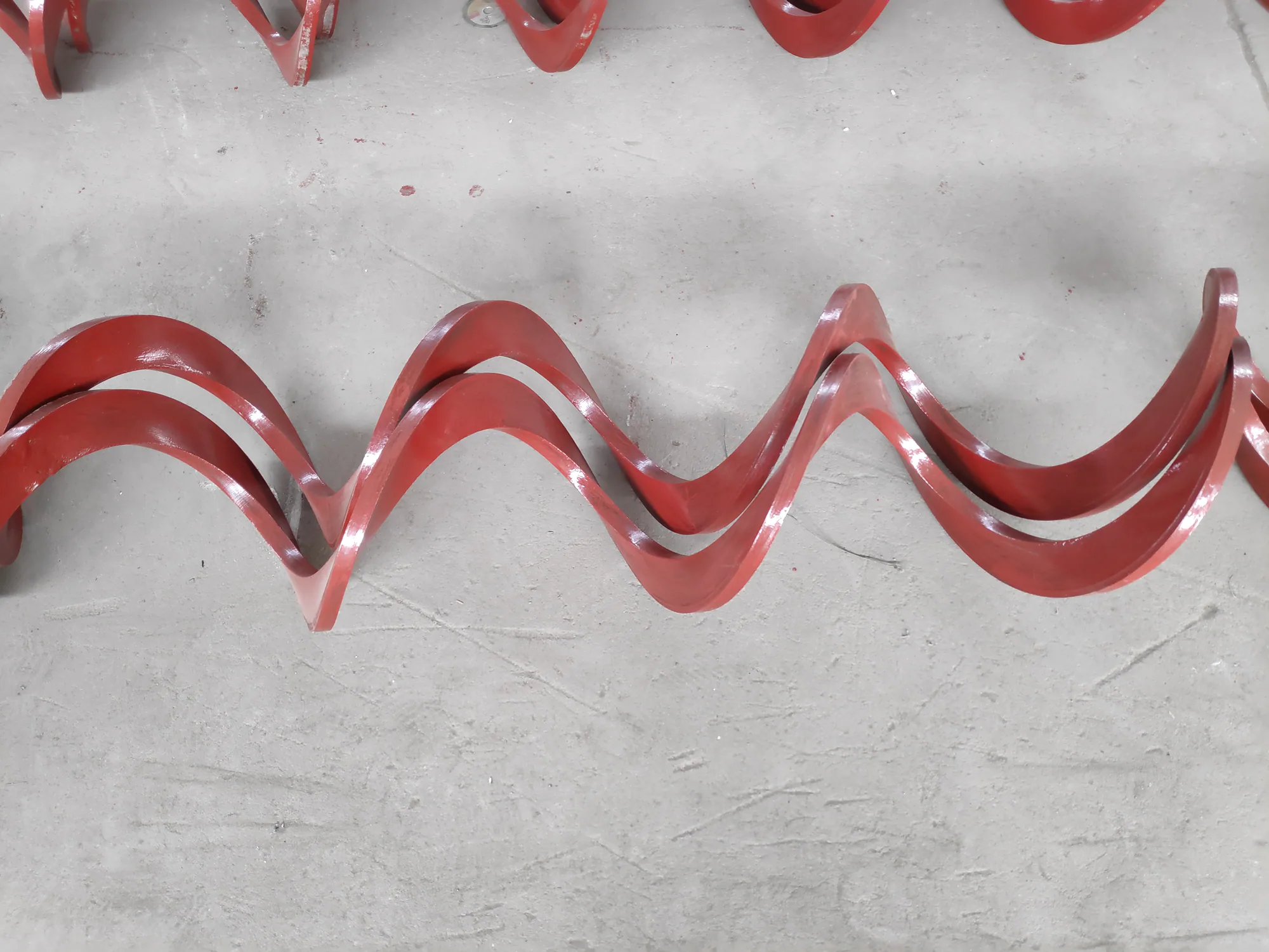
Continuous Constant-Thickness Auger Flight
A continuous mould-winding route for multi-pitch flights where material utilization and consistent wall thickness are priorities.
View details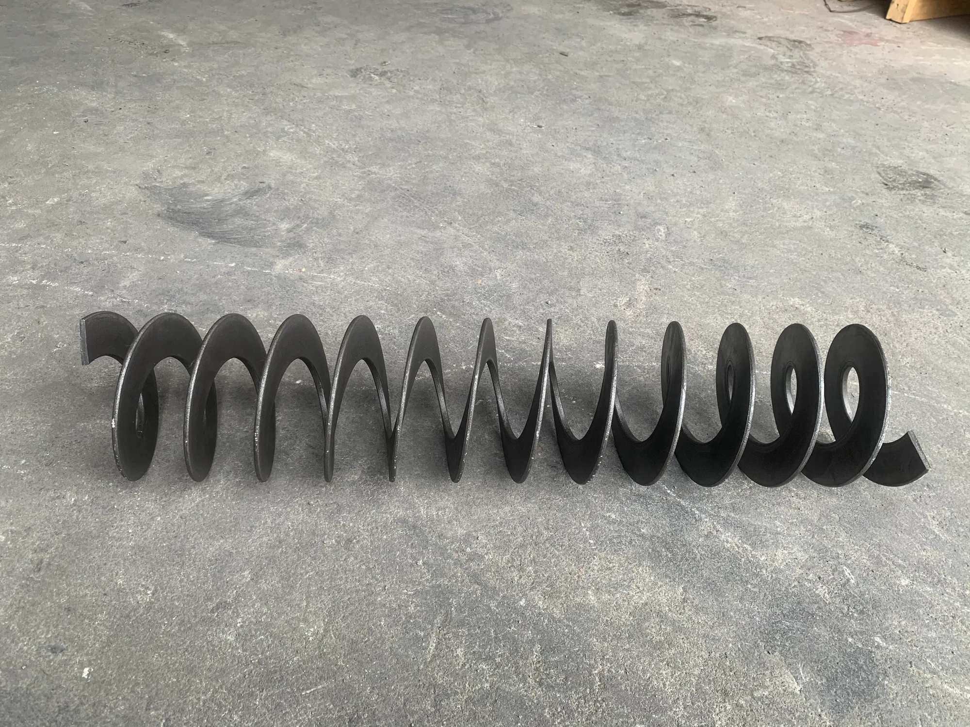
Rounded-Edge Spiral Flight
A helical flight whose rounded edge is part of the specified section, requiring profile dimensions as well as the normal helix geometry.
View detailsEngineering review
Discuss your Shafted Auger Assembly requirement
Share the diameter, pitch, thickness, material, quantity and application. Our team will review the manufacturing route before quoting.