
Forming machinery
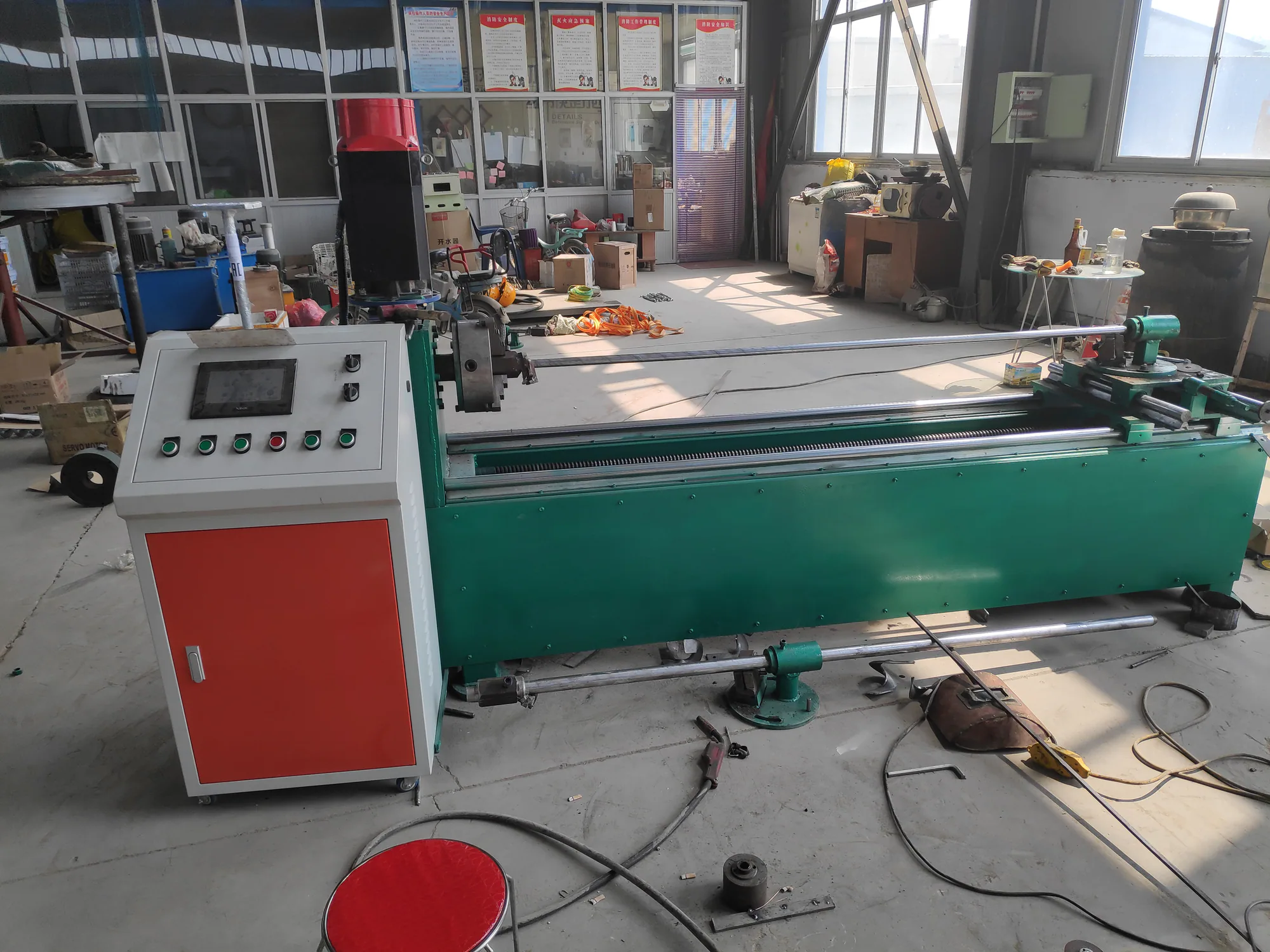
Continuous Screw Flight Winding Machine
Mould-winding machine for continuous constant-thickness screw flight production.
Engineering fit
Built around the dimensions, material and production target that matter
Continuous mould-winding equipment for equal-thickness screw flights where compact installation and parameter adjustment are useful.
Use the stated range as a practical starting point. We confirm the final configuration against your drawing, material and operating conditions.
Discuss this product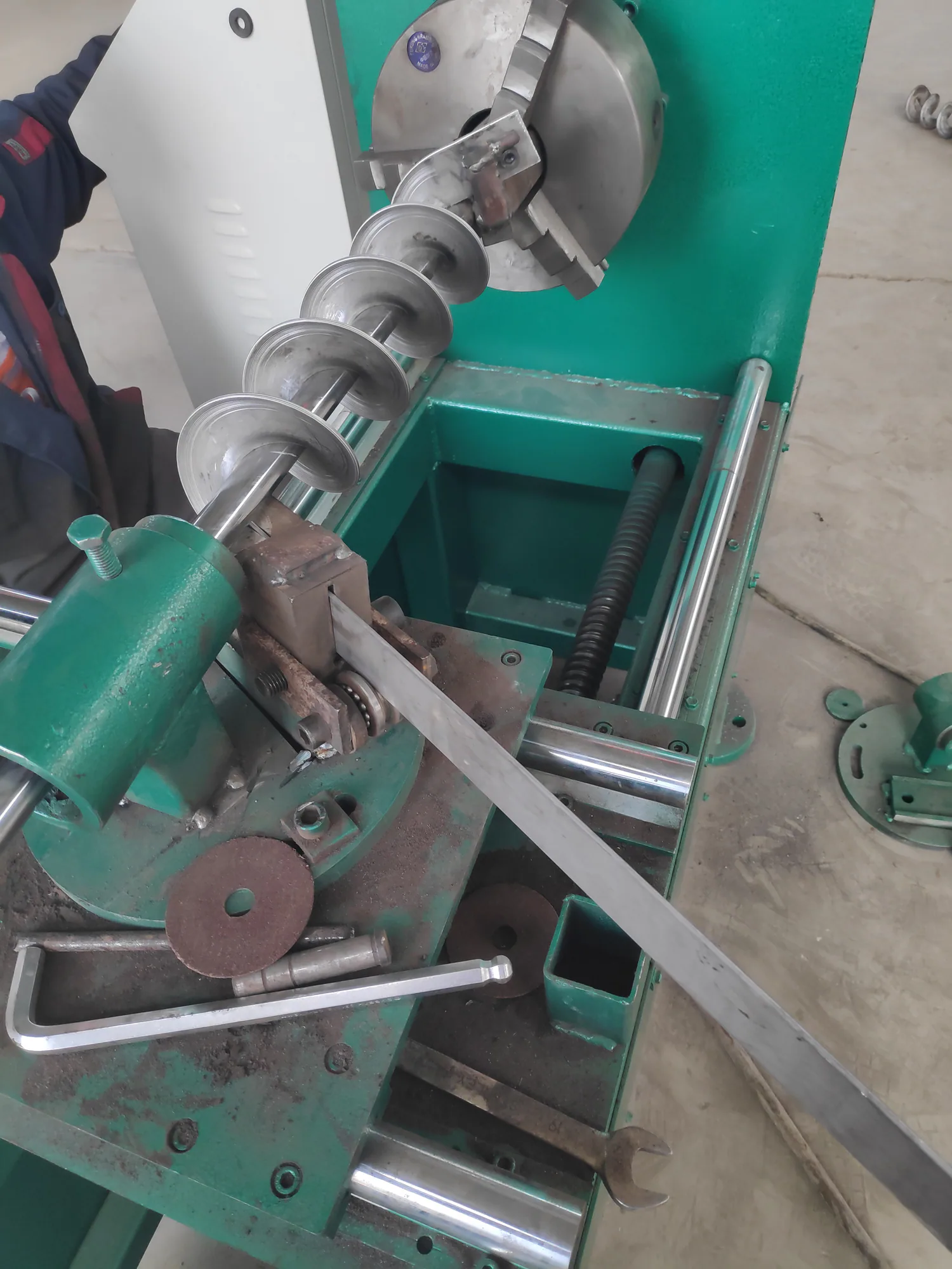
- Continuous flight manufacturing
- Equal-thickness flighting
- Batch production
- Custom spiral forming
Product data
Product Specifications
| Parameter | Specification |
|---|---|
| Available model examples | GX305S and GX80-20S |
| Electrical supply | Confirm voltage, phase and frequency; 380–440 V projects require configuration review |
| Drive | Motor-driven winding spindle, final motor and controls confirmed by configuration |
| Control option | Automatic functions may be configured subject to the agreed machine scope |
| Forming set | Mould, spindle and guides matched to the approved flight drawing |
| GX305S power | 5.5 kW |
| GX80-20S power | 7.5 kW |
| Machine footprint | 3 × 0.9 × 1.2 m |
| Machine weight | 0.8 t or 3.5 t by model |
| Pitch range | 20–120 mm or 100–300 mm by model |
| Maximum OD | 120 mm or 300 mm by model |
| Thickness range | 2–5 mm, 5–8 mm or 10–20 mm |
| Maximum strip width | 30 mm, 60 mm or 70 mm by configuration |
Size reference
Available Dimension Range
Typical sizes are shown below. Custom dimensions can be produced based on your drawing or requirements.
| Parameter | GX305S | GX80-20S | |
|---|---|---|---|
| Power Kw 400V/3Ph/50Hz | 5.5KW | 7.5KW | |
| Machine Size L*W*H cm | 3*0.9*1.2 | 3*0.9*1.2 | |
| Machine Weight Tons | 0.8 | 3.5 | |
| Pitch Range mm | 20-120 | 100-300 | |
| Max OD mm | 120 | 300 | |
| Thickness mm | 2-5 | 5-10 | 10-20 |
| Max Width mm | 30 | 60 | 70 |
Workshop reference
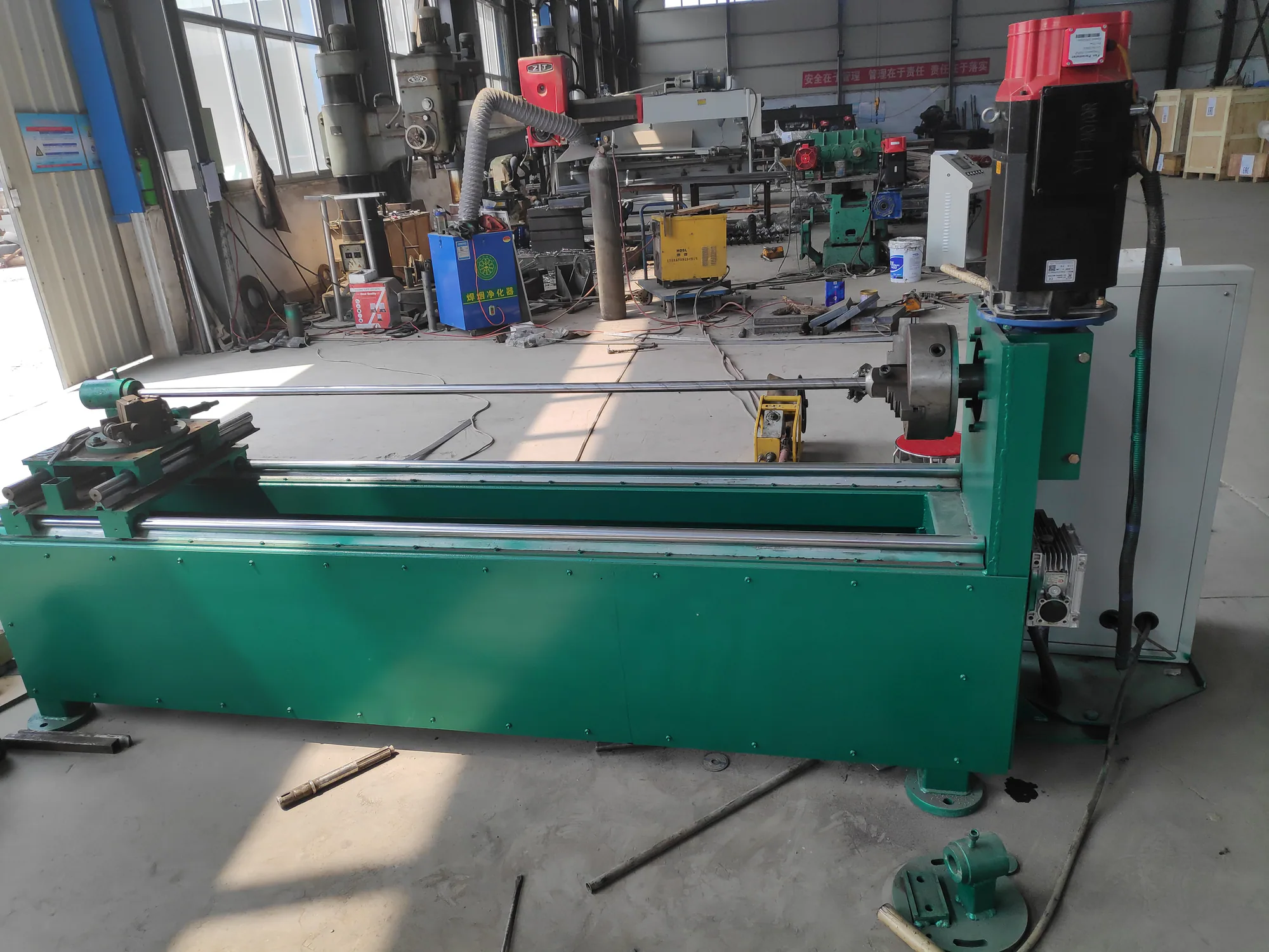
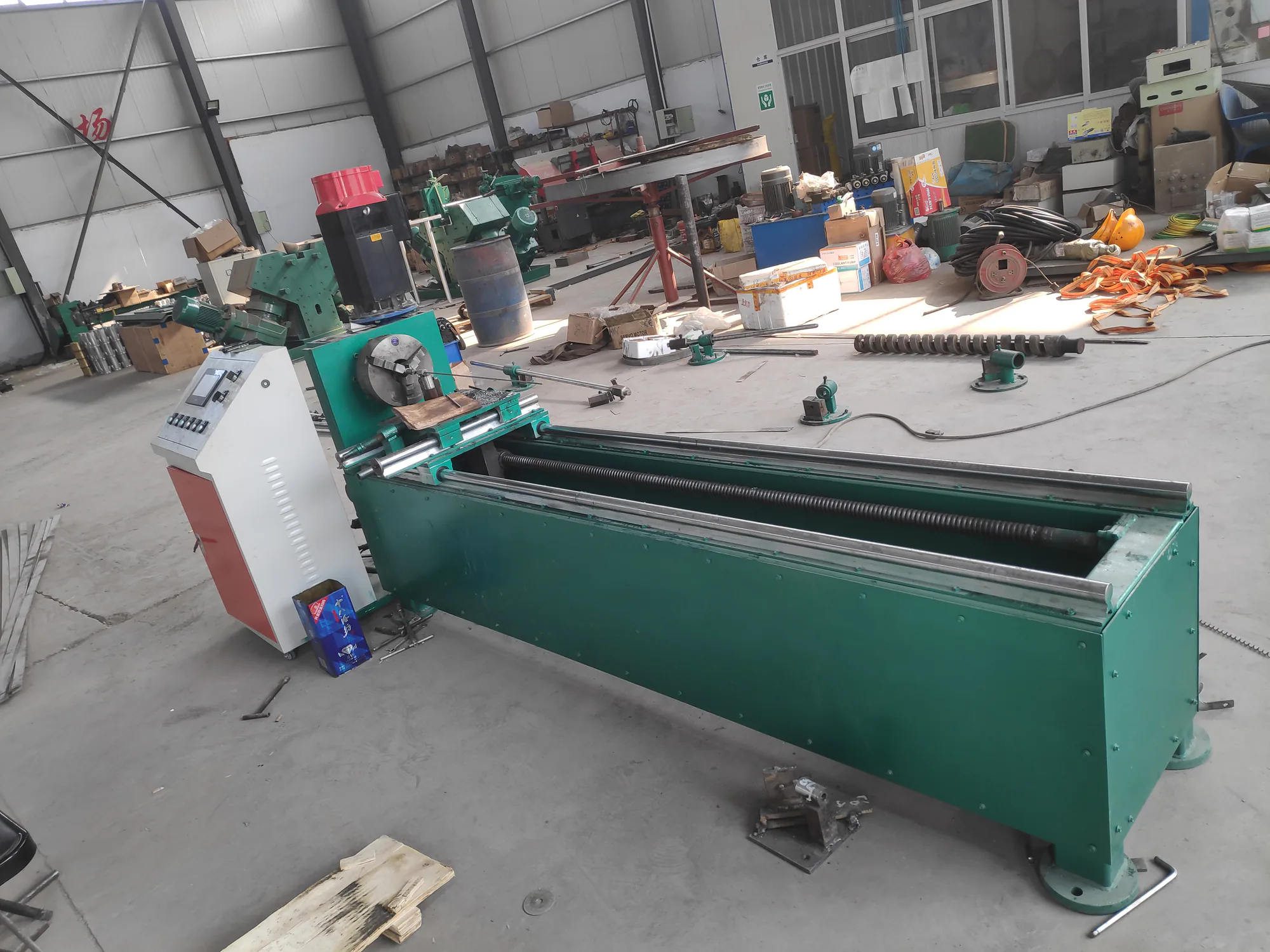
Product and process views
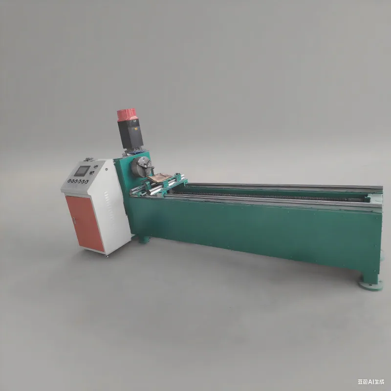
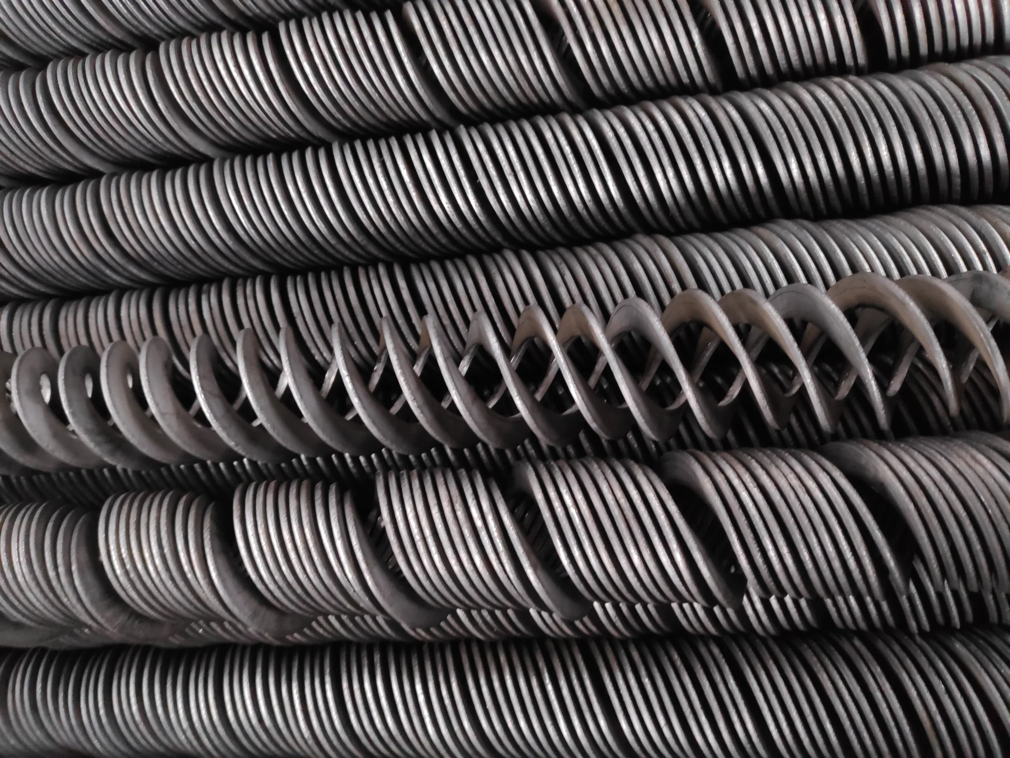
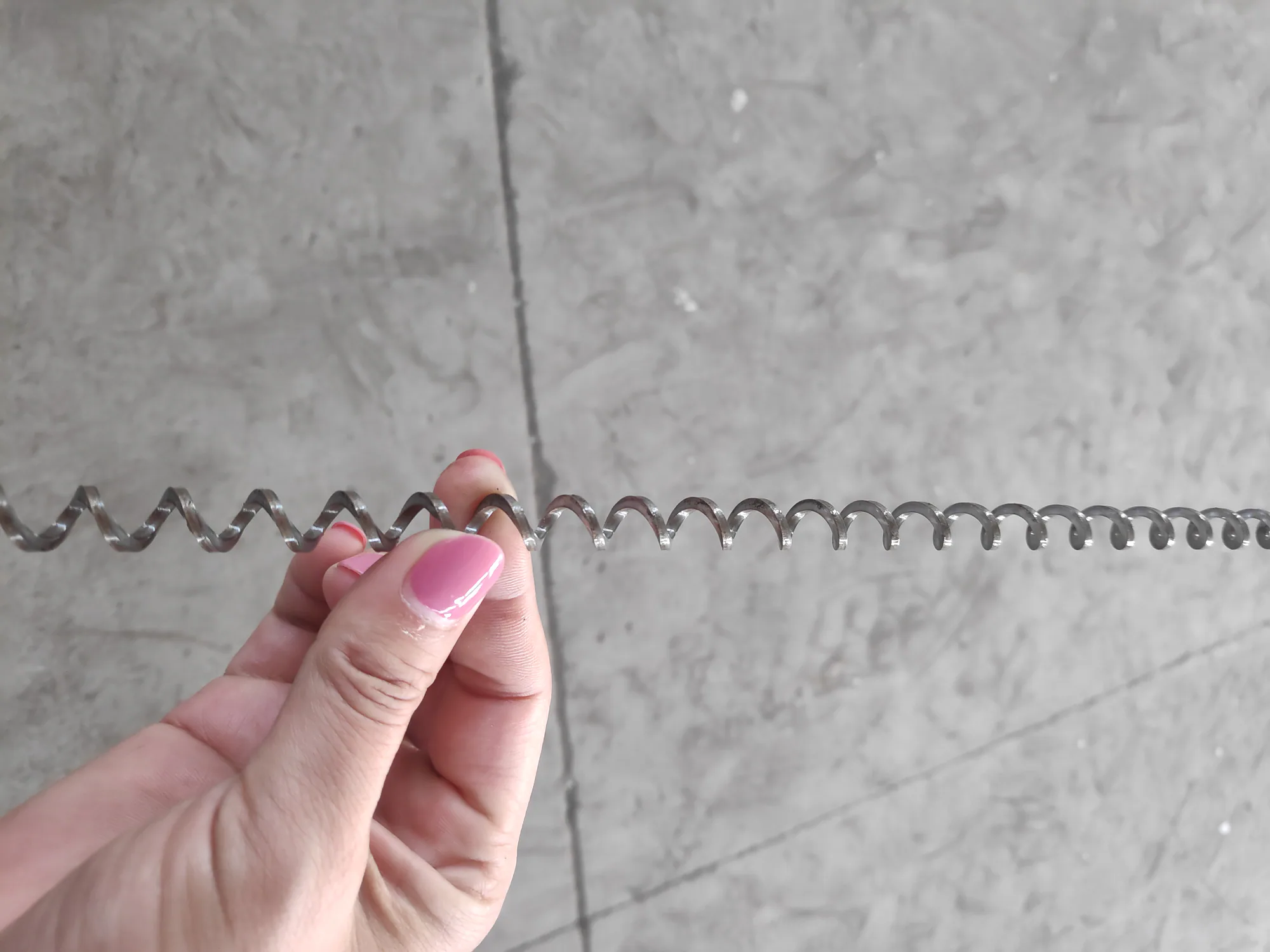
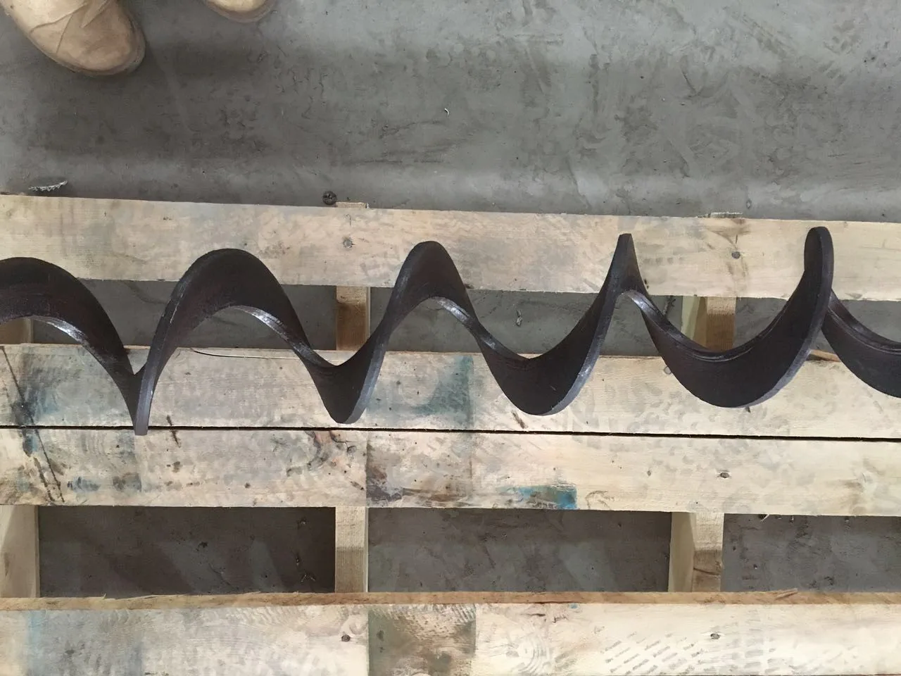
How it works
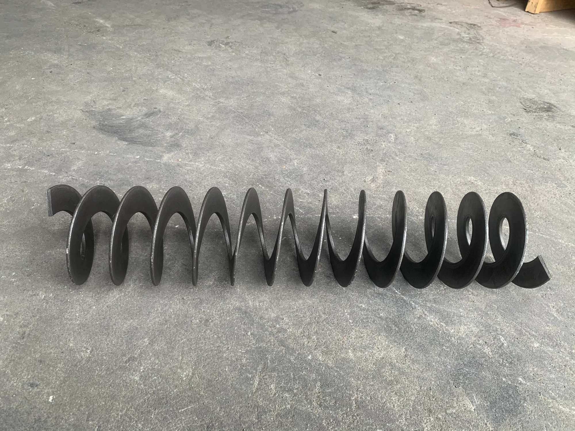
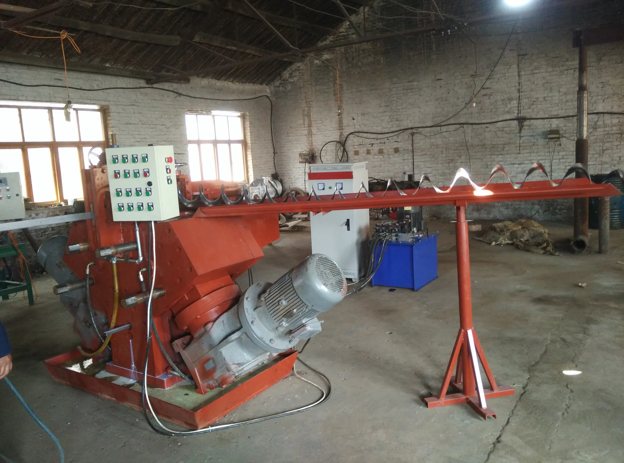
Straightened strip is guided around a winding spindle. The forming mould applies pressure as the spindle rotates, creating a continuous helical structure before cutting to the agreed length.
Forming sequence
The working sequence covers strip loading and straightening, entry guidance, controlled winding around the spindle, dimensional checks and cut-off at the planned length. Material support at the machine exit should be considered for longer flights so the product does not distort during handling.
Practical advantages
The available product material identifies continuous output, parameter consistency, material adaptability and a compact footprint as key advantages of this production route.
Model range at a glance
The listed GX305S and GX80-20S examples cover different pitch, diameter and thickness groups. Rather than treating them as interchangeable, the chosen configuration should follow the required strip width and the finished flight profile.
Electrical and control confirmation
Projects with plant supplies in the 380–440 V range can be reviewed, but voltage alone does not define the electrical package. Confirm phase, frequency, available load, control language and local component or safety requirements. Automatic control functions are available configuration discussions, not a default promise for every machine.
Mould, spindle and guides
The mould and spindle establish the winding route for the selected section, while guides control strip entry and stability. Provide drawings for the planned product range so included forming sets, change parts, setup method and trial material can be listed clearly in the quotation.
Quotation checklist
For a meaningful equipment proposal, send target OD, ID, pitch, material, strip thickness and width, expected length and output requirement. Also include:
- Flight hand, dimensional tolerances and representative drawings
- Coil dimensions, incoming strip condition and loading method
- Required mould and spindle sets across the product range
- Factory voltage, phase, frequency and available connected load
- Preferred control functions and destination safety requirements
- Cut-off method, exit support and downstream assembly process
- Floor plan, lifting access and planned operator position
Before quotation
Frequently asked questions
Use these answers as a starting point. Final geometry, material and equipment scope are confirmed from the project information.
What information is needed to select a winding machine?
Send the flight OD, ID, pitch, thickness, hand and length together with strip width, grade, batch size and representative drawings.
Are the mould and spindle included?
The forming set is matched to the approved flight range. Included moulds, spindle, guides and change parts must be listed in the quotation.
Can the electrical supply be configured for 380 to 440 V?
Projects in that range can be reviewed, but voltage, phase, frequency, connected load and control requirements must be confirmed for the destination factory.
Is automatic control standard?
Automatic functions may be available depending on the agreed configuration. The quotation should define controls, sensors, operating modes and any manual steps.
What trial material should be prepared?
Trial stock should match the intended strip grade, width, thickness and incoming condition. Quantity is agreed from the number of products and tooling sets to be proven.
Continuous Screw Flight Cold Rolling Machine
A model-selection page for workshops planning continuous cold-rolled flight production across different strip widths, thicknesses and output targets.
View details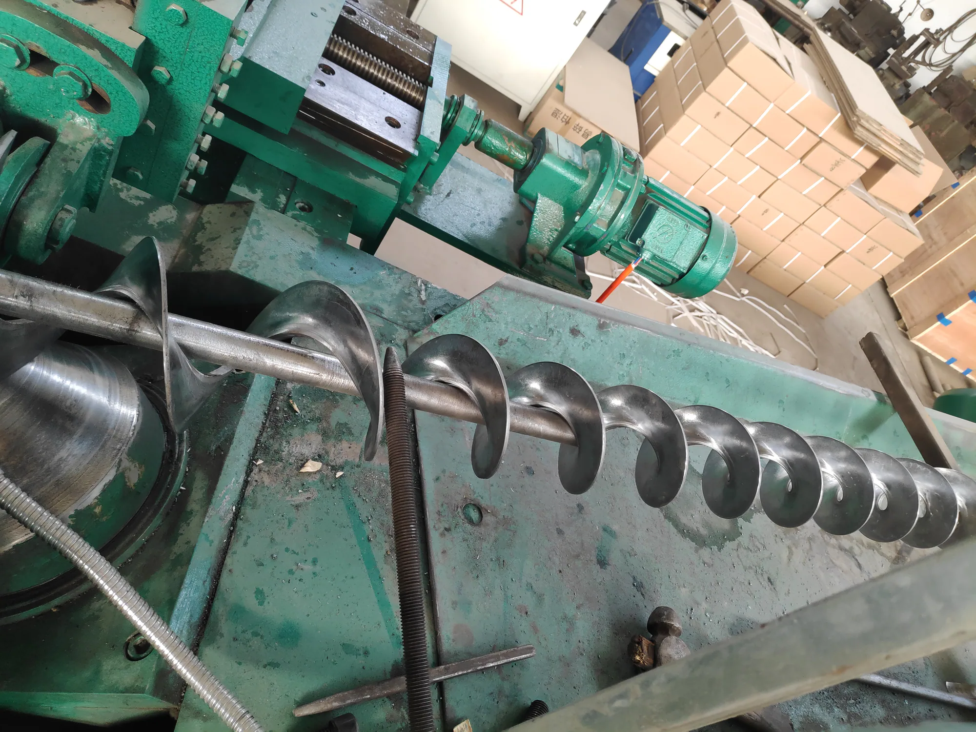
GX130-6M Cold Rolling Machine
A continuous screw flight rolling machine for medium strip widths and repeatable output.
View details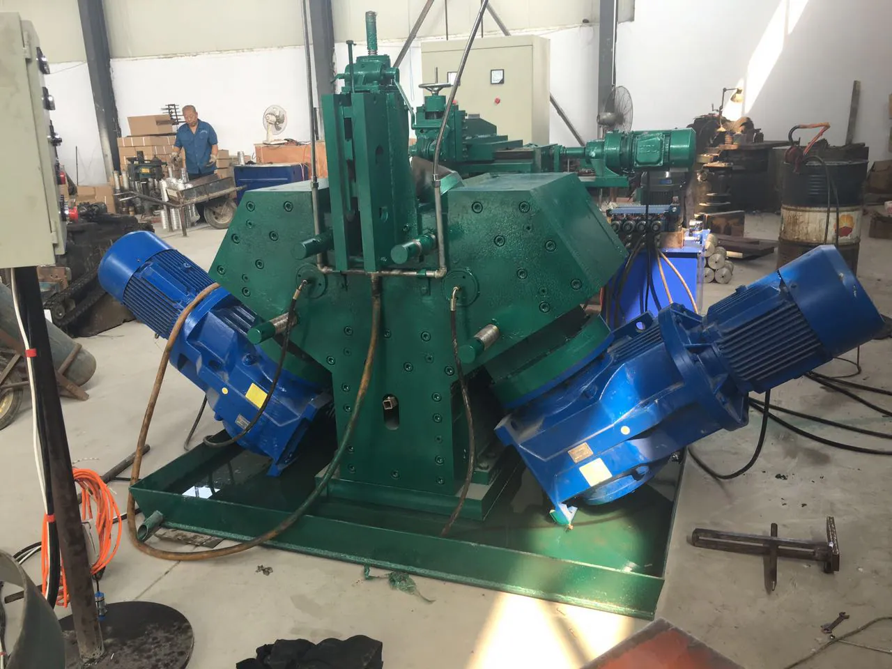
GX150-10L Cold Rolling Machine
A higher-capacity machine configuration for wider strip, larger flight diameters and increased throughput.
View details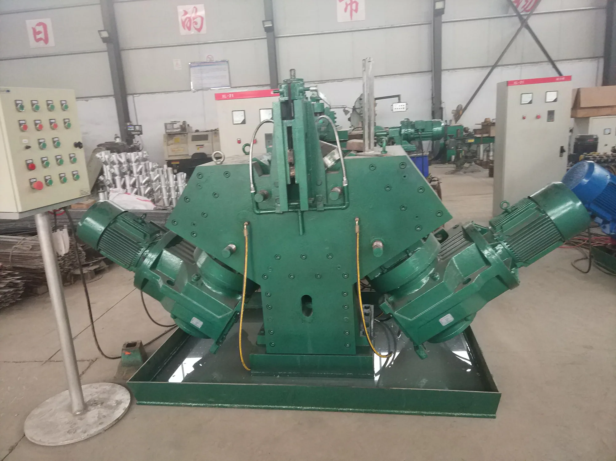
GX60-4S Cold Rolling Machine
A compact continuous cold-rolling option for narrower strip and smaller flight ranges.
View detailsEngineering review
Discuss your Continuous Screw Flight Winding Machine requirement
Share the diameter, pitch, thickness, material, quantity and application. Our team will review the manufacturing route before quoting.